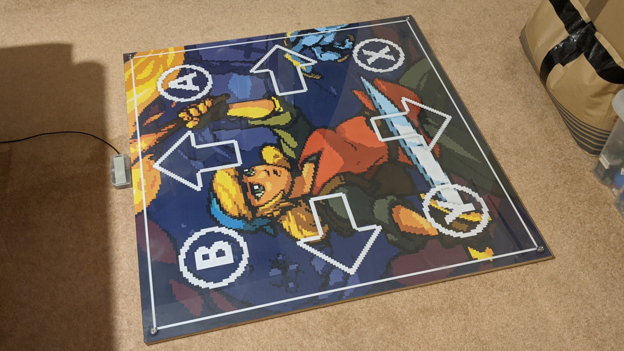
I’ve been using the pictured dance pad since February, and it’s working really well! Here’s how to make one yourself.
I based the pad on Promit Roy’s four-button Velostat design, but mine is made with cheaper materials since I didn’t want to spend too much. Inside, it’s mostly card and sticky tape. If you want to customise this design, I recommend checking out his blog, as he goes into some detail about the impact that different materials can have.
Shopping list
Units are millimetres.
Materials
- Plywood for the base, 890x890 (mine’s about 8mm thick)
- 3mm MDF for the borders, 860x30, 860x30, 890x30, 420x30, 420x30
- 3mm MDF for the centre platform, 280x280
- Copper tape (preferably with conductive adhesive)
- Aluminium foil (optional: use copper tape if you have the money)
- Sticky tape (and plenty of it)
- Newspaper
- Velostat, enough to cover eight 280mm steps
- Copper wire
- 2mm polycarbonate, 890x890
- 5mm-inner-diameter (M5) tee nuts x4
- 5mm (M5) screws x4
- Suitable screw cups x4
- Solder
- A microcontroller that can act as a USB input device. I used a Teensy LC.
- A cable to connect the microcontroller to your PC
- Spray-mount glue
- Pad image on paper or other flexible material, 890x890
- Double-sided adhesive strip (for sticking the control box onto the pad)
- Non-slip material (I used this stuff).
Tools
- Tape measure and pencil, for obvious reasons
- Sandpaper
- Wood glue
- Clamps for holding the wood together while the glue’s drying, and for holding everything together while you’re drilling holes
- Multimeter to make sure everything’s working
- Scissors for cutting tape and card
- Soldering iron, for soldering
- Drill, 5mm, slightly-more-than-5mm bits
- Hammer, for hammering in the tee nuts
I ordered all of the wood (plywood base, MDF borders) from two different online services. I wasn’t very happy with either of them, so I won’t share links. They cut the wood to just about reasonable tolerances, but if you have the tools available I definitely recommend doing this part yourself.
You could use thicker MDF if you wanted. That would slightly reduce the usable area of each step, but would probably feel better. If the MDF was thick enough, you could fit the microcontroller in the border as well, meaning you wouldn’t have to have a box stuck to the front of the pad.
A standard pad would have 280mm steps, but thanks to cost considerations as well as the restrictions of the sites from which I was ordering, the border extends 5mm into the play area on all sides, meaning that other than the centre platform, the steps are actually 275mm in one or both dimensions.
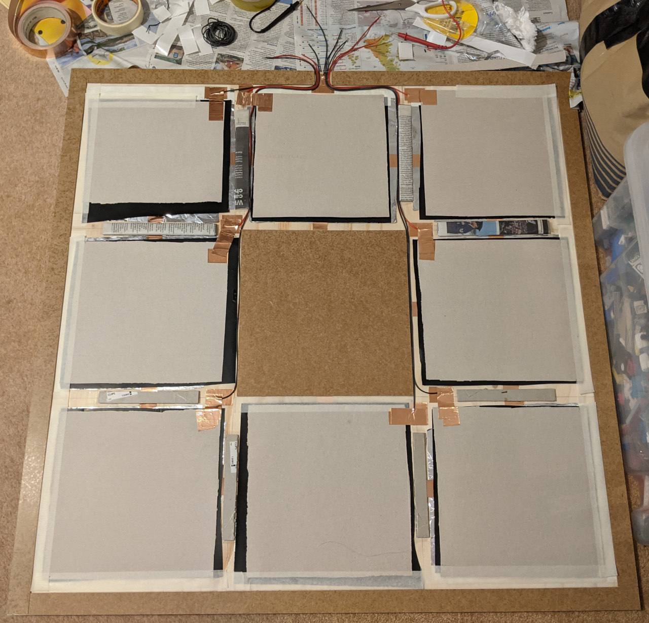
Anyway, after receiving the wood, I sanded the edges to make sure I didn’t hurt myself. Then I glued the MDF borders on and laid out the contacts for the eight panels. Most of the area of each panel is aluminium foil (to save money) and it’s all connected with copper tape. You could use copper or aluminium for the whole thing. Note that there’s a little gap at the top of the up/forward step for the wires to come out of.
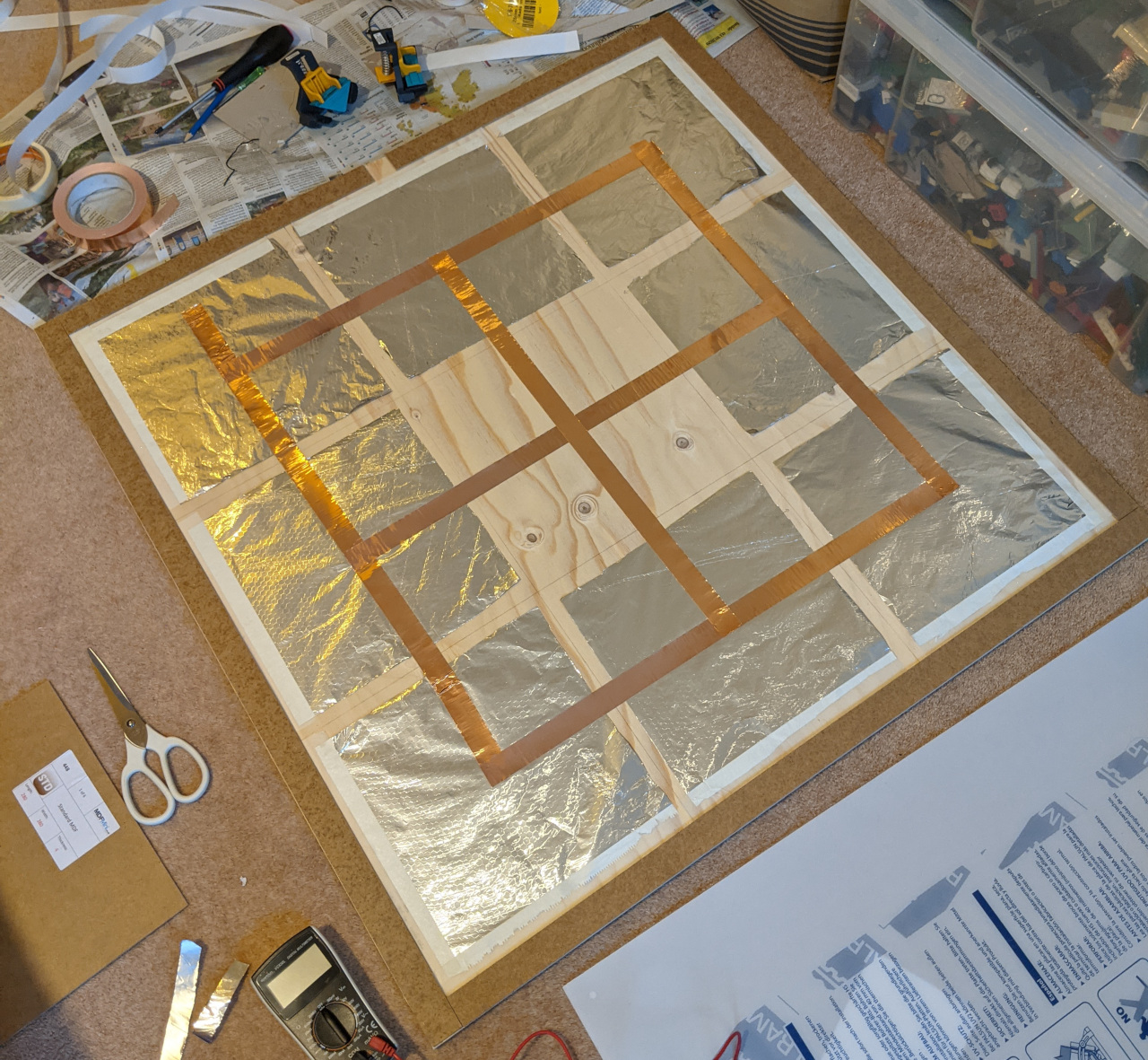
This is the common/ground contact. Use the multimeter to check the resistance across the various panels. You should get very low readings.
Now you can glue down the centre panel. Use a pencil and tape measure to mark where the centre panel and panel dividers should go.
If I’d had any tools, I would have cut smaller bits of MDF to divide the panels. Unfortunately, getting little bits of MDF cut to order was prohibitively expensive, so I rolled up newspaper and stuck bits of card together instead. It’s fine. For our purposes, there really isn’t much difference between 3mm MDF and rolled-up newspaper.
Anyway, I stuck the newspaper down with sticky tape, don’t judge me.
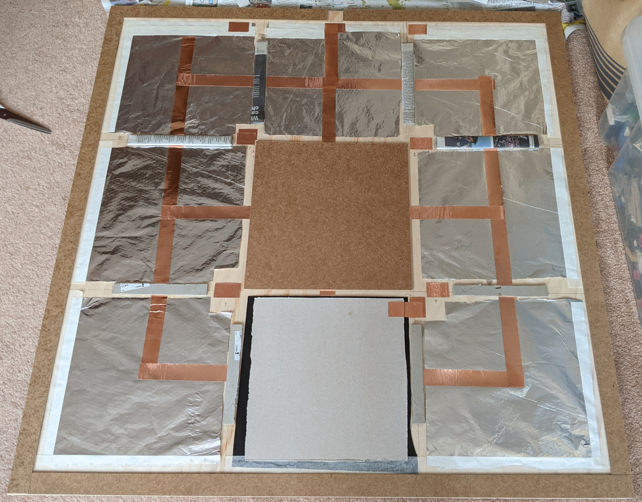
Each step needs a nearby contact. I made a double layer of copper tape next to each piece of aluminium foil. If I was doing it again, I’d put them near the edge of the pad, and take the wires around the outside of the pad, instead of routing the wires between steps.
The next step is to cover each piece of aluminium foil in Velostat; then it’s time to make the upper part of each step’s sensor. I used cereal box card for this, but something a little less flexible would be better. Whatever material you use, cut a piece large enough to cover most of the Velostat, cover the bottom side with copper tape, and wrap a bit of copper tape around to the top side to make wiring easier. I don’t have a photo for this, so here’s a diagram instead.
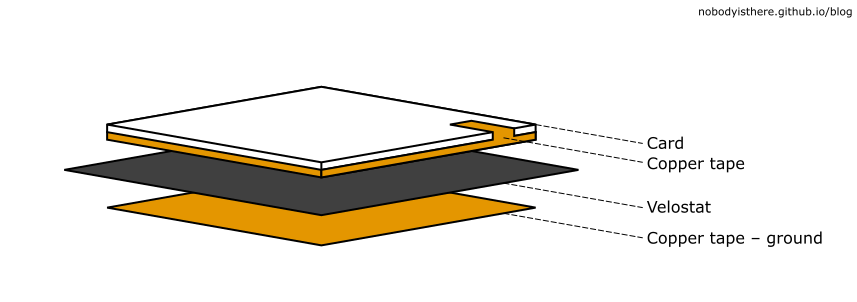
Now just connect the exposed copper tape bits to the contacts you made before, making sure that nothing below the Velostat layer connects directly to anything above.
Solder on some wires, route them through the pad and out of the gap you left in the wood border. Note that as well as a wire for each step, you’ll need to solder a wire to the common contact as well. Just put in a short one at the top of the pad, near the hole.
If you’re as cheap and/or as lazy as me, you’re probably thinking “hey, this copper tape has conductive adhesive; can’t I just stick the wires down with the tape instead of soldering them?”
Don’t do that. The connection will be unreliable and you’ll have a bad time.
Nearly there! Stick everything down with tape. No need to tape every edge of every sensor, but you can if you want.
You should probably test your pad now. Using the multimeter, test each step in turn by measuring the resistance between the common contact and each step contact (or each step’s corresponding wire). When you put your foot on the card, you should see a big drop in resistance (you should see units of Ohms with your foot on the card, and tens or hundreds or more without).
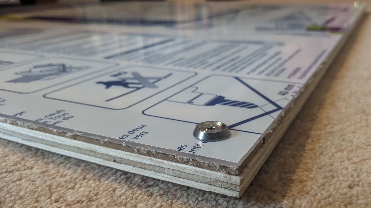
Clamp the polycarbonate sheet onto the pad. Don’t remove the protective film yet. Make sure everything is aligned properly, then drill 5mm holes through the corners.
Take the polycarbonate off (remembering which way round it went) and expand the holes slightly with your slightly-more-than-5mm drill bit. You just need to make the holes wide enough that you can hammer in your tee nuts. Then turn the pad over and do that!
Finally, turn the pad the right way up again, put the polycarbonate back, and screw it on with the screws and screw cups.
It’s finally time to hook up the microcontroller. Solder your wires and plug it into a PC. For the Teensy, I connected the common wire to ground (GND), and the step wires to pins 14–21.
Here’s the code I used, which relies on the Teensy being set up to emulate a keyboard (Tools > USB Type > Keyboard in the Arduino IDE). It’s a slight modification of Promit’s, as I wanted debounce. If you’re just going to be playing Stepmania, you don’t need to bother with the debounce code (the game can do it for you), but you’ll probably need it if you want to play anything else.
I bound the eight buttons to the arrow keys, enter, backspace, control, and shift. Make sure those work properly. Have a go, play some games, tweak the code, make sure it all works.
Now it’s time for the final touches. Remove the protective film and spray-mount the image onto the back of the polycarbonate. Put all the exposed electronics in a box. I used a couple of adhesive strips I got with my doorbell to stick the box to the front of the pad.
Finally, you’ll probably want to glue some non-slip material to the bottom. I used the wood glue for this and it worked fine.
Congratulations, your pad is complete!